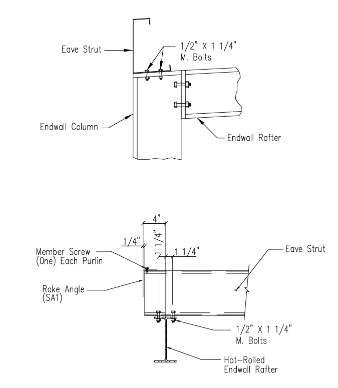
This detail outlines the attachment of roof purlins and eave struts at a rigid frame/I-Beam end-wall. The upper diagram/animation shows the purlin attachment, and the lower diagram shows the eave-strut. Also shown in this detail is the installation of the rake angle at both the purlin and eave-strut and a flange brace at the purlin.
This connection is more common than SD9. In this scenario the purlin is shown installation to the rafter and the Eave-strut is installed to the top of the column. Larger buildings may have a purlin that is also installed to the top of the column.
Unless called out differently in the building construction drawings, the end of the purlin only requires (2) 1/2″ A307 bolts and nuts; however, (4) bolts can be installed if desired. These should be installed diagonally, and a 1/2″ washer needs to be installed on the purlin side at the slotted hole.
The Eave strut will extend to the building’s steel line and uses (4) 1/2 “A307 bolts with washers. This connection is through the bottom flange of the eave-strut rather than through the web. On low slope buildings it is possible to rest the eave strut on top of the rafter while placing bolts. However, a strap or rope should be used to prevent the eave-strut from sliding off of the rafter until it is secured with bolts and nuts.
Please see detail SD1 for a description and animation of the installation of the rake angle at the purlin. For a clean look we recommend that the rake angle be miter cut at the eave-strut. While the rake angle will be concealed with panel and trim it will be visible on the inside of the building if the building is not insulated, if the building is insulated leaving the rake angle square cut and not cut on slope the insulation can be torn during installation on the sharp edge of the rake angle.
You should receive your estimated quote by email shortly. Please keep in mind that this is just an estimate and does not include snow loads, wind loads, county specific code requirements, delivery or design specific engineering calculations related to the structural soundness of the building.
Text Messaging
Would you like a response via text message? Opting into SMS indicates you agree to receive SMS messages regarding your request from Great Western Buildings. Message and data rates may apply. Message frequency may vary. To end messaging from us, you may always reply with STOP. You may also reply with HELP for more information.